
Experimental Fluid
Dynamics Laboratory
Facilities
Prof. Ekmekci's research group has three main experimental facilities where tests are conducted: a large-recirculating water tunnel for aerodynamic tests, an anechoic wind tunnel for aerodynamic and aeroacoustic tests, and an anechoic room for acoustic tests.
1. Water Tunnel
This is a recirculating flow facility, continuously providing a uniform flow along its 5-m long test section. The walls of the test section are made of Plexiglas material to allow optical access to the flow. This facility can operate in free-surface mode (with no top covers) or as a closed tunnel (using top covers). It is known that compared to a wind tunnel flow facility, the water flow facilities have the advantage of slowing down the flow dynamics are thereby enabling the capture and time- resolved analysis of highly unsteady flow behavior. This facility is therefore used to simulate the flow fields around scaled models of various bodies, including cylinders, landing gears, automobiles, Ahmed bodies, micro air vehicles, etc.
The technical details of this facility can be summarized as follows:
| Tunnel Type: Recirculating Water TunnelFacility Modes: (1) Free-surface channel (removing the top covers) (2) Closed tunnel mode (using top covers) Test Section Details: |
Speed Range: 0.03 m/s - 0.8 m/sMaximum Reynolds Number: Re = 880,000 per meter @ T = 25°C (Water temperature is controllable using a thermocouple and a tankless water heater) Turbulence Level: |
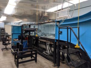 Water tunnel facility
2. UTIAS Hybrid Anechoic Wind Tunnel
This facility is suitable to conduct aeroacoustic and aerodynamic measurements. Its test section is interchangeable between three operation modes: (1) an open jet test section, (2) hard-walled test section, and (3) test section with tensioned Kevlar side walls. The test section is enclosed within an anechoic chamber, which provides a suitable environment for a broad spectrum of aeroacoustic measurements in open-jet and Kevlar-walled tunnel configurations. The technical details of this facility can be summarized as follows:
| Wind tunnel modes: (1) Open jet enclosed within an anechoic chamber (2) Tensioned-Kevlar walled test section within an anechoic chamber (3) Hard-walled test sectionSpeed Range: 10 m/s - 75 m/s (in open-jet configuration) 10 m/s - 60 m/s (in Kevlar walled configuration) 10 m/s - 60 m/s (in hard-walled configuration) Cross-Section: Turbulence Level: |
Anechoic chamber Outer dimensions: 6 m (W), 6 m (L), 3 m (H) Inner dimensions: 4.9 m (W), 4.9 m (L), 1.8 m (H)Wall treatment: Triangular-shaped acoustic foam wedges Cutoff frequency: |
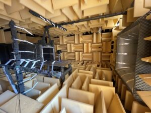 Anechoic wind tunnel in open-jet configuration
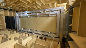 Anechoic wind tunnel with tensioned-Kevlar walled test section
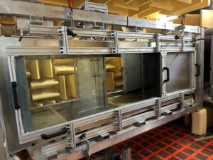 Hard-walled wind tunnel test section with the 30P30N model inside it
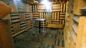
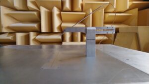
3. Anechoic Room
This facility is used to conduct noise measurements in no-flow (quiescent) conditions. The technical details of this facility can be summarized as follows:
| Facility: Anechoic RoomAnechoic Room Dimensions: 2.83 m, 3.97 m, 2.07 m Wall Treatment: Cutoff frequency: |
 |
Laser-Based Quantitative Flow Diagnostic Systems
1. Planar- and Stereo- Particle Image Velocimetry (PIV) System:
The PIV system provides a non-intrusive laser optical technique to make successive measurements of velocity fields over any planar region of interest in the flow. The acquisition rate of this system is 14.5 Hz. During the analyses, this velocity data is used to calculate other flow features, such as, vorticity, frequency spectra of velocity fluctuations, streamlines, the dominant flow structures, etc.
As an example, the flow field acquired via PIV around a car model is shown below (contours of velocity magnitude and streamline topology are shown overlapped).
![]()
2. Volumetric 3-Component Velocimetry (V3V):
The V3V system allows measurements of 3-component velocity fields in volumetric regions. The measurement volume can reach as high as 140 mm x 140 mm x 100 mm, and the data acquisition rate is 7.5 Hz. This technology is particularly useful in investigations where volumetric flow information is essential.
The image shows velocity vectors superimposed on the contours of vorticity. As can be seen, a vortex ring is detectable from this data. (Image from TSI Inc)
![]()
Acoustic Measurement Systems
1. Linear Microphone Array Systems:
We use linear microphone arrays to conduct noise directivity measurements. The picture below is shows linear microphone arrays set up in the anechoic wind tunnel.
2. Phased Microphone Array Systems:
We have a 63-element phased microphone array system designed and built by our team at EFDL. The array's design is based on multi-arm spiral design scheme with an equal aperture area for each microphone. We implement this system for noise source localization. The picture below shows this 63-microphone array.
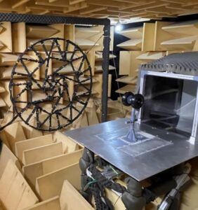
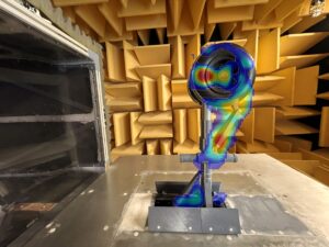
A picture of the 63-microphone phased array system and the noise source localization results obtained processing the array data using the delay-and-sum algorithm.
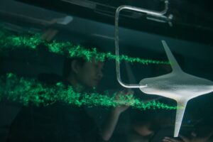
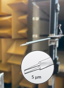
Hydrogen Bubble Visualization Systems
These systems are useful for visual identification of the coherent flow structures. In this technique, hydrogen bubbles are produced at the surface of a thin wire through electrolysis. These bubbles, which are very small, effectively follow the flow, allowing its visualization. We have the capability to run the systems in continuous and pulsed mode, have multiple high definition video cameras for image capture, and high intensity LED light (with color filters) and laser illumination sources.
An example data from the visualization of a vortical structure forming around the landing gear model is depicted below. As can be seen, one can detect visually the coherent vortex structures with this technique.
![]()
Dye Visualization Systems
This system provides a visual means to inspect flow streaklines for the identification of coherent flow structures in the flow. We have a 6-colour dye well available.
Pressure Measurement Capabilities
We have several steady and unsteady pressure measurement capabilities:
1. Steady pressure measurement capabilities:
In addition to the 16-port Scanivalve DSA3217, we have an in-house built 128-port pressure scanner. The 128-port scanner is based on the thermally compensated MKS 220DD pressure transducer, and it utilizes a series of electronically controlled solenoid valves in order to cycle between the different channels.
2. Unsteady pressure measurement capabilities:
We use remote microphones that allow us to measure unsteady surface pressure from 24 pressure taps at the same time. This is made possible by our in-house built amplifier and signal conditioners. For higher frequency measurements, we have 5 miniature surface pressure transducers (Kulite LQ-062) and a (Kulite KSC2) signal conditioner for higher frequency measurements.
Hot Film and Hot Wire Anemometry Systems
These systems are used to measure velocity fluctuations at a single point in the flow, which then are used to conduct accurate spectral analyses. We have multiple hot film and hot wire anemometry probes with adequate signal processing equipment.
Motorized Traverse Systems
The lab has several motorized linear and rotary traverse systems along with all the necessary hardware and software to generate controlled motion of models wherever needed.
Data Acquisition and Processing Units
We have several data acquisition and processing computers with all the necessary hardware and software.
Model Design and Manufacturing Capabilities
We have a 3D printing facility that enables easy and fast manufacturing of some models to be tested. The CAD designs of the test models to be printed are also made in house.
![]()